
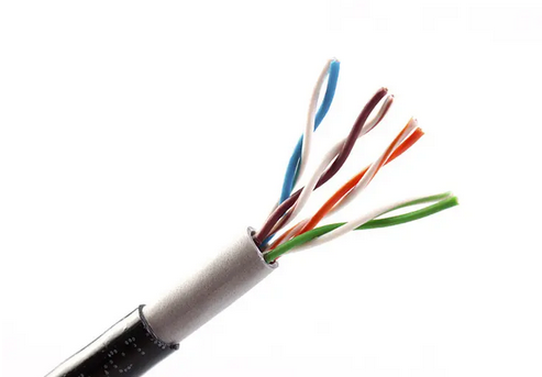
Today, let me explain the detailed structure of marine Ethernet cables. Simply put, standard Ethernet cables consist of conductor, insulation layer, shielding layer, and outer sheath, while armored cables add an inner sheath and armor layer between the shielding and outer sheath. Clearly, armored cables provide not only extra mechanical protection but also an additional protective inner sheath. Now, let’s examine each component in detail.
1. Conductor: The Core of Signal Transmission
Ethernet cable conductors come in various materials including tinned copper, bare copper, aluminum wire, copper-clad aluminum, and copper-clad steel. According to IEC 61156-5:2020, marine Ethernet cables should use solid annealed copper conductors with diameters between 0.4mm and 0.65mm. As demands for higher transmission speeds and stability increase, inferior conductors like aluminum and copper-clad aluminum are being phased out, with tinned copper and bare copper now dominating the market.
Compared to bare copper, tinned copper offers superior chemical stability, resisting oxidation, chemical corrosion, and humidity to maintain circuit reliability.
Conductors come in two structures: solid and stranded. Solid conductors use a single copper wire, while stranded conductors consist of multiple thin copper wires twisted together. The key difference lies in transmission performance – since larger cross-sectional areas reduce insertion loss, stranded conductors exhibit 20%-50% higher attenuation than solid ones. The gaps between strands also increase DC resistance.
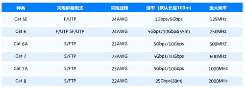
Most Ethernet cables use either 23AWG (0.57mm) or 24AWG (0.51mm) conductors. While CAT5E typically uses 24AWG, higher categories like CAT6/6A/7/7A often require 23AWG for better performance. However, IEC standards don’t mandate specific wire gauges – well-manufactured 24AWG cables can still meet CAT6+ specifications.
2. Insulation Layer: Protecting Signal Integrity
The insulation layer prevents signal leakage during transmission. Following IEC 60092-360 and GB/T 50311-2016 standards, marine cables typically use high-density polyethylene (HDPE) or foamed polyethylene (PE Foam). HDPE offers excellent temperature resistance, mechanical strength, and environmental stress cracking resistance, making it widely applicable. Foamed PE provides better dielectric properties, making it ideal for high-speed CAT6A+ cables.
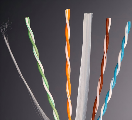
3. Cross Separator: Reducing Signal Crosstalk
The cross separator (also known as cross filler) is designed to physically separate the four twisted pairs into distinct quadrants, effectively reducing crosstalk between pairs. Typically constructed from HDPE material with a standard diameter of 0.5mm, this component is essential for Category 6 and higher-grade cables that transmit data at 1Gbps or faster, as these cables demonstrate greater sensitivity to signal noise and require enhanced interference resistance. Consequently, Category 6 and above cables without individual pair foil shielding universally incorporate cross fillers to isolate the four twisted pairs.
In contrast, Category 5e cables and those employing pair-shielded foil designs omit the cross filler. The inherent twisted-pair configuration of Cat5e cables provides sufficient interference protection for their more limited bandwidth requirements, eliminating the need for additional separation. Similarly, cables with foil-shielded pairs utilize the aluminum foil’s inherent capability to block high-frequency electromagnetic interference, rendering the cross filler unnecessary.
The tensile strength member plays a critical role in preventing cable elongation that could compromise performance. Industry-leading cable manufacturers predominantly utilize either fiberglass or nylon cord as the tensile reinforcement element in their cable constructions. These materials provide optimal mechanical protection while maintaining the cable’s transmission characteristics.
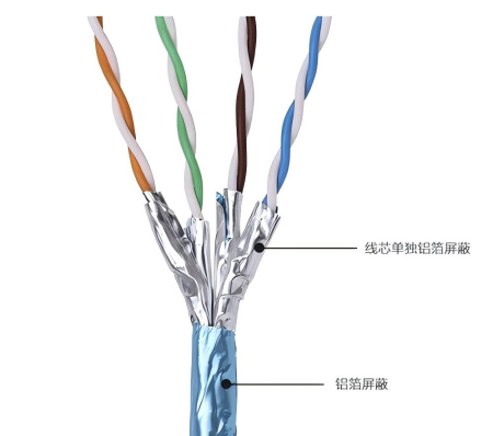
4. Shielding Layer: Electromagnetic Protection
Shielding layers consist of aluminum foil and/or braided mesh to block EMI. Single-shielded cables use one aluminum foil layer (≥0.012mm thick with ≥20% overlap) plus a PET mylar layer to prevent current leakage. Double-shielded versions come in two types: SF/UTP (overall foil + braid) and S/FTP (individual pair foil + overall braid). The tinned copper braid (≥0.5mm wire diameter) offers customizable coverage (typically 45%, 65%, or 80%). Per IEC 60092-350, single-shielded marine cables require a drain wire for grounding, while double-shielded versions use the braid for static discharge.
5. Armor Layer: Mechanical Protection
The armor layer enhances tensile/crush resistance and improves EMI shielding. Marine cables primarily use braided armor per ISO 7959-2, with galvanized steel wire (GSWB) offering high strength and heat resistance for demanding applications, while tinned copper wire (TCWB) provides better flexibility for tight spaces.
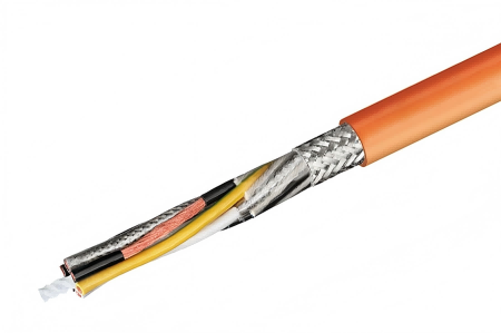
6. Outer Sheath: Environmental Shield
The outer sheath must be smooth, concentric, and removable without damaging underlying layers. DNV standards require thickness (Dt) to be 0.04×Df (internal diameter) +0.5mm, with 0.7mm minimum. Marine cables primarily use LSZH (low-smoke zero-halogen) materials (SHF1/SHF2/SHF2 MUD grades per IEC 60092-360) that minimize toxic fumes during fires.
Conclusion
Every layer of marine Ethernet cables embodies careful engineering. At OW CABLE, we’re committed to advancing cable technology – feel free to discuss your specific needs with us!
Post time: Mar-25-2025