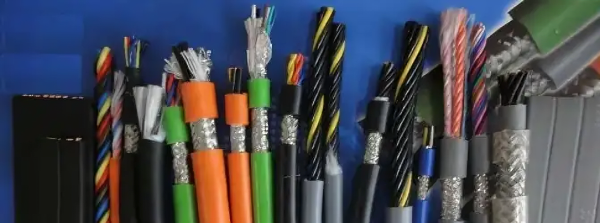
A drag chain cable, as the name suggests, is a special cable used inside a drag chain. In situations where equipment units need to move back and forth, to prevent cable entanglement, wear, pulling, hooking, and scattering, cables are often placed inside cable drag chains. This provides protection to the cables, allowing them to move back and forth along with the drag chain without significant wear. This highly flexible cable designed for movement along with the drag chain is called a drag chain cable. The design of drag chain cables must take into consideration the specific requirements imposed by the drag chain environment.
To meet the continuous back-and-forth movement, a typical drag chain cable consists of several components:
Copper Wire Structure
Cables should choose the most flexible conductor, generally, the thinner the conductor, the better the flexibility of the cable. However, if the conductor is too thin, there will be a phenomenon where tensile strength and swinging performance deteriorate. A series of long-term experiments have proven the optimal diameter, length, and shielding combination for a single conductor, providing the best tensile strength. The cable should select the most flexible conductor; in general, the thinner the conductor, the better the flexibility of the cable. However, if the conductor is too thin, multi-core stranded wires are needed, increasing operational difficulty and cost. The advent of copper foil wires has solved this problem, with both physical and electrical properties being the optimal choice compared to currently available materials in the market.
Core Wire Insulation
The insulation material inside the cable must not stick to each other and needs to have excellent physical properties, high swing, and high tensile strength. Currently, modified PVC and TPE materials have proven their reliability in the application process of drag chain cables, which undergo millions of cycles.
Tensile Center
In the cable, the central core should ideally have a true center circle based on the number of cores and the space in each core wire crossing area. The choice of various filling fibers, kevlar wires, and other materials becomes crucial in this scenario.
The stranded wire structure must be wound around a stable tensile center with the optimal interlocking pitch. However, due to the application of insulation materials, the stranded wire structure should be designed based on the motion state. Starting from 12 core wires, a bundled twisting method should be adopted.
Shielding
By optimizing the weaving angle, the shielding layer is tightly woven outside the inner sheath. Loose weaving can reduce the EMC protection ability, and the shielding layer quickly fails due to the breakage of the shielding. The tightly woven shielding layer also has the function of resisting torsion.
The outer sheath made from different modified materials has various functions, including UV resistance, low-temperature resistance, oil resistance, and cost optimization. However, all these outer sheaths share a common characteristic: high abrasion resistance and non-adhesiveness. The outer sheath must be highly flexible while providing support, and, of course, it should have high pressure resistance. The outer sheath made from different modified materials has different functions, including UV resistance, low-temperature resistance, oil resistance, and cost optimization. However, all these outer sheaths share a common characteristic: high abrasion resistance and non-adhesiveness. The outer sheath must be highly flexible.

Post time: Jan-17-2024

